begins to overtake the weight of the system.
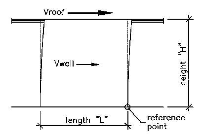
| Basic Shear Wall Diagram | |
|
|
| This second example is for a wall with higher shear
loading that begins to overtake the weight of the system. |
| Resulting Forces | |
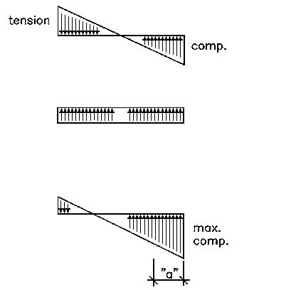 |
|
| Note that as lateral loads increase, the maximum tension
and compression in the triangular force pair increases.
At the bottom diagram, adding the two resulting forces
together |
For lateral loads (triangular force pair)...
Mot = (Vroof * H) + (Vwall * H/2)
For vertical loads (rectangular force)...
Mr = (Total Weight * L/2)
And finally...
"a" = (Mr-Mot)/(Total Weight)max. comp. = (2/3)*(Total Weight/a)
| Alternate Result | |
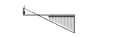 |
|
| The bottom diagram can be redrawn to show a single
force in place of the triangular distribution. This is the first step in understanding the use of hold-downs in shear walls. |